3D-CAD
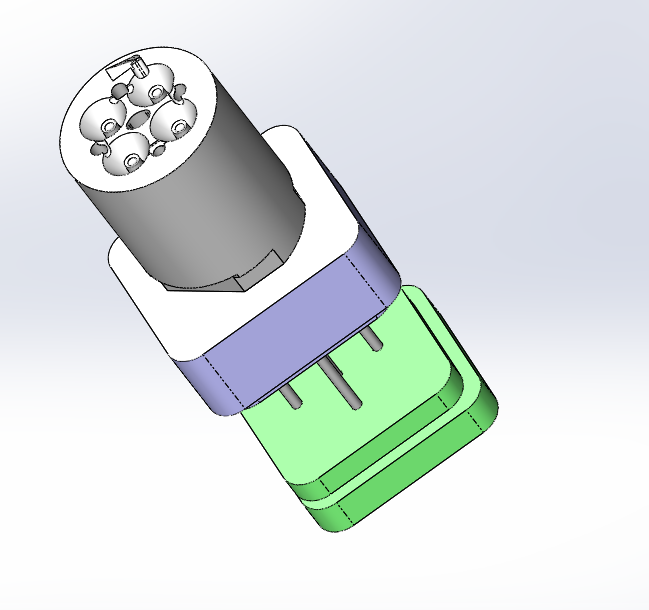
We use 3D CAD (solidworks) in our factory for model and tool design. The use of 3D software makes it more easy to transfer the design to the toolshop by means of STEP files which the machines use for the creation of their tool-paths. That said, still 2D drawings are used, as molding tool building – specifically for optic parts- comes with a lot of GD&T (geometric dimensioning and tolerancing) that will need to be specified to the craftsmen who will need to be able to analyze these GD&T for final assembly purposes of the tooling. Another important aspect is drafting of the part. If not enough attention is given to this aspect it can make automated production very difficult as you will experience difficulties of the lens loosening from the mold. 3D CAD is of great assistance to detect issues and analyze potential problems during the design phase.
Optics calculation and simulation
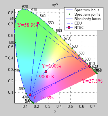
Most of the designs are subject to optical analysis (if customer has no capability of performing this type of analysis). The type of LED used in the application is obviously an important factor. For most commercially available high performance LED’s the manufacturer provides ray-sets. This ray-set is used in the optical simulation software (like for example ASAP, TracePro or LightTools) to determine the optical behavior of the lens in relation to this LED source. Elementary optics like colorimetry and photometrics is complicated matter. Contact us if you have issues you would like to discuss. We have resources available capable of delving into your issue.